MATV – Free or for a price?
In the rearview mirror, the mystery here is why it took entrepreneurs like Chuck Dolan and Irving B. Kahn until 1964 to figure out that the largest, most concentrated, CATV market in the United States was right there in the boroughs of New York City.
Indeed, well before 1952 it was obvious that the insatiable demand for reliable television service would continue to grow. In spite of the reception problems facing apartment residents, many residents in larger cities could receive a few stations with rooftop antennas, window-ledge antenna, or various other devices. Programming such as "Pabst Blue Ribbon Bouts" (Wednesday evenings on CBS), ABC's "Wednesday Night Wrestling", and NBC's Friday-evening "Gillette Cavalcade of Sports - Boxing" were among the most popular fare.
But problems arose:
- One trade publication reported that "evening time popular programming so reduces the [apartment dweller's] line voltage that people have a 7-inch picture on a 10-inch CRT!"
- University of Michigan Professor Edward Stasheff — a former New York-based television executive — famously observed that New York's sewers abruptly overflowed during commercial breaks when thousands of toilets were flushed simultaneously.
Such stories notwithstanding, many apartment residents were not able to receive television signals. Anecdotal evidence illustrates the problems faced by these residents:
- Courts were inundated by lawsuits as residents denied access to rooftops (or television sets as in Detroit) claimed a loss of First Amendment rights.
- Numerous restaurants and taverns equipped their establishments with television receivers to attract customers. Most of them purchased projection systems — the "large screen" option of the day.
- Parents without TV at home would bring their children to these businesses — even those serving alcoholic beverages — to watch television. This situation prompted several New Jersey city councils to adopt regulations prohibiting minors from being in any facility that served liquor.
It was obvious that a technical solution was needed. A master antenna television system (MATV) was one answer, certainly better than the nightly rooftop brawls. An MATV system would distribute the signals received by a single antenna to multiple, unrelated, TV viewing locations.
The Copyright Issue
As the television industry developed during the 1950s, two issues began to attract the attention of the television program producers and their copyright attorneys:
MATV systems: does a MATV (or CATV) system which carries a television
program (as part of the signal of a television broadcast station) to multiple
subscribers infringe on the copyright of the program owner?
Public places: does the exhibition of a television program in a public
place — for example, a restaurant or a tavern — infringe on the
copyright of the program owner?
In late 1948, Columbia Law Review published an epic opinion piece that addressed the second question : "It is illegal for taverns, hotels, motion picture theaters, dance halls and other public places to exhibit television."
But this same copyright question applied equally to cable TV systems. It would not be resolved until 1976, when Congress finally addressed the issue with the enactment of the Copyright Act of 1976. |
|
RCA had taken the lead in 1947 with a television version of their 'Antenaplex' system, a product for distributing AM radio signals ("Radio By Wire") that RCA had developed and patented in 1931. Master Antenna Television (MATV) was a direct descendent of the AM radio Antenaplex system, redesigned to carry the higher frequencies and wider bandwidths required for transmission of television signals.
Although RCA had patented the concept, it was quickly copied by a host of other firms. Anyone could locate antennas, cable, and, by 1948, functional (if not yet totally suitable) amplifiers. Other factors, such as signal attenuation attributable to coaxial cable or resistive devices, could be calculated by anyone familiar with basic physics.
A summary report by Ira Kamen in the April 1949 issue of Radio & Television News, titled "Television Master Antennas," covered the basics and detailed three competitive system designs already well past the experimental stage. All three examples were in the New York City area, indicating that Kamen had written the article in late 1948.
Kamen cited an interesting reason why MATV had not grown more rapidly as of late 1948. He wrote:
| "...there is considerable resistance [to MATV] by the realty field which expects the television industry to furnish television receivers with built-in aerials in the near future.
"Realtors constantly refer to the relatively limited use of radio master antenna systems today in multiple dwellings because of the development of home radio receivers with built-in 'loop antennas'.
"The realtors feel hesitant about spending money for television master antennas since they feel that perhaps they may be made obsolete by new indoor television antennas." |
Kamens's opinion notwithstanding, there is every reason to believe that 'master antennas' for AM radio reception installed in apartment buildings sooner than later generated enough income in the early-period service to at least retire any debt incurred in construction and maintenance.
In actual use, receiver-with-antenna radio sets worked rather poorly. But if apartment building owners and developers chose not to make the investment in 'Antenaplex' or a similar signal-distribution systems, apartment residents had no choice: they lost out either way.
This is the same mindset that delayed the installation of MATV systems.
Moreover, other factors came into play. The technology of MATV in 1947-50 was frightfully bad. And it was a costly investment: each channel required a separate set of receiving equipment — antenna and single channel amplifiers. At the time, New York City had seven operating VHF television stations, each of which required a separate set of reception equipment. Building owners and developers again chose not to invest in MATV.
But this situation was about to change. A year or so after Kamen's April 1949 summary report, he discovered that some firms were pushing MATV systems as self-liquidating investments — investments which would, over time, actually turn a profit. In in a relatively short period of time — less than twelve months — building owners and realtors changed their minds. From what had been regarded as an unnecessary expense in the fantasy that TV sets would appear with adequate built-in antennas, they figured out that the cost of an MATV system could be paid for by monthly fees for the service.
The bottom line here, for me, is that MATV systems that charged for both installation and monthly service set the pattern for the early CATV operators we discussed in Part 2. People would pay to have clear, clean, TV reception.
Milton Jerrold Shapp, the founder of Jerrold Electronics, got that message before most others.
Later, in May 1950, describing 'master antenna system' progress, Kamen wrote:
| "Business organizations that finance installation of master antenna systems in buildings operate like telephone companies and make an initial installation connection charge and a monthly service charge to the tenants in the building. Systems for this type of financing are usually installed so that the antenna service can be disconnected without entering the tenant's apartment. (Radio Electronics, May 1950) |
Perhaps this is the business model we have been searching for: provide an antenna service, charge a connection fee and a monthly maintenance?
Inasmuch as the article appeared in May 1950, it would be logical to assume that the practice described had been in use from at least sometime in 1949. Was there a 'Jerrold' or 'RCA' element in this business?
As we noted in Part 3, firms such as Jerrold had introduced indoor antennas in a variety of configurations: devices that tapped into the electrical wiring, and "magic carpets" that could be laid flat on the floor, tacked to a ceiling, or hidden behind a picture frame. Some were miniature versions of outdoor antennas mounted on swivels that sat atop TV sets or shelving. By mid-1949, Jerrold offered "amplified indoor antennas" – a settop booster amplifier with protruding rabbit-ear whips.
None of these devices work particularly well: in a significant majority of attempts, reception only became worse (Radio Electronics October 1949). MATV finally became a solution of last resort.
Searching for a TV reception solution
Late in 1948 — about the same time Parsons in Oregon, Davidson in Arkansas and Walson in Pennsylvania were 'pioneering' CATV — Kamen noted that the following MATV design and installation firms were active in New York City:
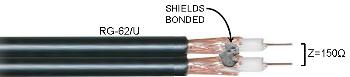
- Amy, Aceves & King. This company had made a patent application for a system "claimed to serve twenty television and FM receivers from a single antenna array." They were concentrating on six-story (18-unit) buildings in Brooklyn. They appear to have been using some form of "figure-8" 93-ohm coaxial cable such as RG-62/U (4 dB loss per 100' at 200 MHz) run on the exterior of the building, with passive resistive devices feeding through the
exterior walls (or wood window sills) into individual units. For the connection between the passive device and the TV set, they apparently used the same 93-ohm coax or 150-ohm twinlead.
The figure-8 coax provided shielding from direct pickup while approximated a characteristic impedance of 150 ohms.
There is no discussion of amplifiers in their 'patent-pending' system, although they did install
separate dipole antennas, with reflectors, for low band (channels 2, 4, 5) and high band (at the time, channels 7, 11, plus Newark's WATV-13).
- Intra-Video Corporation of America. This company took a different approach with its patented (#2,394,917) system. Rather than one low- and one high-band antenna, Intra typically installed a separate receive antenna for each TV channel so that each antenna could be aimed for optimum performance. Sometimes a single antenna could be used for two stations at the same azimuth.
Intra-Video also manufactured a single-channel 'booster amplifier' to increase the channel's signal level before a combining network that combined all channels (six in New York) to a common distribution network.
The patent claimed 30 dB. of "interference rejection" from signals emitted by nearby local oscillators. Of course, even if this claim were accurate, it might not have been true for local oscillator signals backfed through antenna feedlines and picked up by other nearby antennas.
In fact the 'booster amplifier' was a six-tube single-channel 'strip amplifier' nestled into a master housing that provided mechanical support and power for up to seven such strips. Strips were available in two configurations:
| CONFIG |
PURPOSE |
BASSPAND |
| TV |
One NTSC TV Channel |
6 MHz. |
| FM |
FM Band |
20 MHz (88-108 MHz.) |
Using this product, an installer could customize each installation to match the available signals: up to seven TV stations, or six TV stations plus FM.
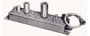
Jerrold Model PMA Single Channel Amplifier. Intra-Video Corporation of America offered a similar amplifier for use in MATV systems. |
|
If you see a similarity here between Intra's products and the Jerrold model MC-1 tube type single channel 'strip amps' (1950+), it is no coincidence. Intra (from photos accompanying the Radio-Television article cited above), appears to have been using a coaxial cable, perhaps 70-ohm, as the report mentions the ability to match (at TV sets) "300-ohm balanced or 70-ohm unbalanced TV set inputs."
- RCA. RCA's (TV-FM-AM) Antenaplex system design appears to have been 'first to
market' but significantly more costly that either of the two competitors mentioned in Kamen's Radio Electronics article cited above.
Like Intra-Video, RCA typically installed a single antenna for each channel in order to minimize interference and obtain a ghost-free image. Each antenna was connected to a single-channel booster amp. Photos in Kamen's report indicate that booster amps were available in three configurations:
| CONFIG |
TUBE COMPLEMENT |
BASSPAND |
| TV low band |
Two |
6 MHz. |
| TV high band |
Three |
6 MHz. |
| FM |
Four |
20 MHz (88-108 MHz.) |
These amplifiers were rated for an output capability of 1 volt (+60 dBmV). Of course, subsequent combining networks would have reduced the level of each channel to around +50 dBmV. This level would been quite adequate to feed every unit in an 18-unit building.
All three of these approaches were designed and put into service well before of the development of broadband amplifiers that would pass the TV low band (54-88 or 54-108 MHz) and the TV high band (174-216 MHz) in one device.
 At the outset, RCA was using 50-ohm coaxial cable for distribution networks, taking advantage of the widespread availability of RG58 and RG8/U after World War II. Over time, however, RCA switched to 70-ohm (RG59 or RG11) cable.
RCA also produced high-isolation matching and coupling transformers to drive multiple feeder lines attached to building walls as shown in the drawing at right. RCA claimed 50-dB isolation between outlets, although in this writer's opinion, that seems a bit overstated.
While most TV and FM sets available in the 1947-1950+ era were fitted with 300-ohm balanced antenna input connections, a growing number of sets were equipped with 70- or 75-ohm inputs. RCA produced set-matching transformers for inputs of 300,
70, and 50 ohms.
Of course, the actual input impedance of the TV tuners of the day varied widely depending the design of the tuner and the frequency to which it was tuned. Accurately matching the actual input impedance of any particular TV set was at best a crapshoot.
RCA's attempt to offer AM, FM and TV in one distribution network was apparently unique. And it was not without new problems for the AM segment users. Harmonics of the television set's horizontal sweep oscillator (a 15.75-KHz sawtooth) coupled back into the AM signals.  RCA attempted to control it by installing separate distribution lines — one for AM and one for TV/FM — and by installing special three-output wall outlets (AM, FM, and TV). These efforts were apparently unsuccessful. According to Kamen, "... [horizontal sweep oscillator] 'beeps' appeared across the [AM] band, making it difficult to use." He further noted that this problem was "especially severe with AM receivers using built-in loop
antennas."
RCA attempted to control it by installing separate distribution lines — one for AM and one for TV/FM — and by installing special three-output wall outlets (AM, FM, and TV). These efforts were apparently unsuccessful. According to Kamen, "... [horizontal sweep oscillator] 'beeps' appeared across the [AM] band, making it difficult to use." He further noted that this problem was "especially severe with AM receivers using built-in loop
antennas."
And this is where we started: receivers with 'built-in' antennas!
At the time, many TV receiver designers were at least attempting to solve the built-into-set antenna riddle. And if they couldn't actually accomplish the goal, their efforts at least provided the merchandising folks with 'one more feature' to hype to the unsuspecting public.
Most designs involved either a 72- or 300-ohm 'dipole' attached somewhere on or inside the cabinet. With high expectations, Philco announced a 'fan dipole' using what amounted to aluminum foil, which, it was hoped, would 'broadband' the inside-cabinet antenna. It did not.
In any case, it would have been difficult to stuff a broadband resonant dipole for low band channels inside a cabinet whose total end-to-end dimension seldom exceeded five feet. Few television cabinets were large enough.
Compounding the problem was the proximity of the antenna to other components buried inside the cabinet. Components such as as the vertical scan circuits and high-voltage circuits would generate noise signals. Large pieces of metal, such as metallic CRT shells, would detune the antenna — even one which might have performed favorably in free space.
The location of the TV set within the premises also affected reception. It seems unlikely that a resident would be to willing to move the receiver around the room looking for a 'hot spot' for the best signal. Not to mention having to avoid real hot spots: one 1949 receiver carried a printed warning: "Do not place this receiver under or near a thermostat."
The real estate people continued to hold out hope for a 'built-in-aerial' solution but it was not going to happen.
A Business Plan Emerges
If it is proving difficult to isolate "one inventor" who successfully constructed the first 'CATV' system, as a technological achievement, what about the business aspect? As we have seen, many (hundreds in fact) entrepreneurs worked out the challenge of selecting a high spot for the antenna and connecting less favored homes with some type of wire. But which one first began to impose a monthly service charge?
Consider the three "I was first" contenders we discussed in Part 2 of this narrative:
- Davidson charged his first home $3.00 a month for connection to a Channel 4 yagi antenna mounted on a 100-foot tower, but we cannot be certain when he began charging.
- Parsons initially did not charge a monthly fee, but by 1951 he was doing so. But again, when he began charging a monthly fee is uncertain.
- Walson, always the most difficult to accept based upon his selective memory and his lack of reliable records (said to have been destroyed in a 1952 fire), was perhaps his own worst enemy in the proof department. Like Davidson and Parsons, no reliable evidence exists to indicate when he began charging a monthly fee.
Mary Alice Mayer Phillips, a doctoral candidate at Northwestern and the author of the 1972 book CATV: A history of community antenna television, interviewed Walson twice (1968 and 1970) during the course of her research. In Chapter 2 of the book, she notes that during the 1968 interview, Walson claimed to have had 727 subscribers by 1948, and to have been charging $2 per connection (plus a $100 installation charge) per month by 1949.
But in the 1970 interview, he made no such claim, in effect retracting the claims he had made in 1968.
During the 1968 interview, Walson also claimed to have begun his "three-channel system in the spring of 1948." Yet we know from FCC sources that Philadelphia's WCAU-TV {Channel 10} began operation on May 22, 1948. It would have been difficult to deliver three channels at a time when there were only two functioning stations — even if we assume that he had managed to solve the twinlead and amplifier problems.
If we give Walson the benefit of the doubt, we can assume that 'Spring 1948' would be sometime between March 21 and June 20. If Walson and his crews had indeed connected 727 homes during this 90-day interval, they would have to have connected eight homes per day working seven days per week. While possible, this seems unlikely. Walson's recollections do not fit the puzzle.
Yet it is clear that at some point Walson did begin collecting monthly fees from subscribers. According to his 1968 interview with Phillips, he provided free service to customers who had purchased TV sets from his store. If we posit that even that arrangement constitutes a form of payment by the subscriber, we can accept the claim that Walson was collecting a fee by 1949.
But the exact date remains uncertain.
In short, all three contenders eventually began to impose a monthly charge, but we cannot reliably determine which one was first.
If CATV was to be a business, some type of plan — the mechanics of supplying a service and being paid for it — had to evolve. Phillips makes it clear that Parsons was collecting an installation fee for his service as early as "before January 1949", and that at or before that date Davidson had at least one paying 'subscriber.' Walson originally offered a no-fee connection to his aerial system to any home that had purchased a TV set from his appliance store.
But by relying on unshielded twinlead for his transmission lines, Walson shot himself in the pocketbook. Residents who had not purchased television sets from him soon discovered that a modest antenna attached to the front porch and aimed toward his passing twinlead would pick up a signal capable of producing a viewable picture.
This, of course, is not surprising: unshielded conductors radiate. In the absence of a concentric shield to prevent signal radiation, Walson's twinlead distribution network radiated television signals. Such factors as impedance mismatches and early-learning-curve mechanical connections no doubt exacerbated the problem.
There were, of course, many others going through the same learning curve: it was not rocket science. Entrepreneurs in places like Eldred and Mapledale, Pennsylvania serve as examples. Mapledale's James Reynolds had become so enthused by magazine articles from 1930-50 describing 'British Piped TV' — and how operators of those services were charging connection fees and a subscription fees — that he adopted a similar model for his CATV operations. After constructing a CATV system in Mapledale, he expanded to nearby communities of Sandy Lake, Cochranton, Utica and Polk, all in Pennsylvania.
But Reynolds left no date-verifiable documentation to qualify his possible claim to having been first.
Typically, these CATV pioneers all built their systems with "off-the-shelf" hardware. By 1948, TV signal boosters had become a fast-selling item in the $30-40 range. Some, such as the Tel-a-Ray Pre-Amplifier, from Tel-A-Ray Enterprises, Inc. of Henderson, Kentucky, consisted of two components:
- An antenna-mounted amplifier, usually mounted directly to the driven element of the receiving antenna.
- An indoor-installed power supply to provide power (filament and B+ voltage) to the generally
short-life tubes at the antenna.
These components were connected either by the twinlead (thereby presenting several new maintenance problems) or by a separate powering cable. Tel-a-Ray provided a four-conductor flatline cable to carry power to the amplifier and to return the preamplified signal down to the reception equipment.
In late 1950, Tel-a-Ray was apparently the only manufacturer to offer antenna-mounted amplifiers, but within six months dozens of competitors appeared. Reports in Radio Electronics/Radio TV News tell of fringe-area or terrain-shielded would-be-viewers cascading as many as 14 of the 'booster' devices in series in an attempt to 'get pictures'!
By 1950, an "antenna war" was in full swing in the trade press, each antenna
manufacturer claiming that their products provided the best reception in distant locations.
RTVN, March 1952
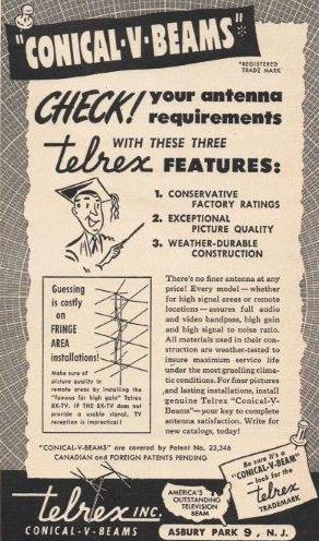
Advertisement for Telrex "Conical-V-Beans" antenna. Radio & Television News, March 1952. |
What started out in mid-1949 with advertising claiming "100-mile reception" had by 1952 mushroomed to "300 miles" (and in tiny fine print "over water") for an antenna known as the Telrex 4-Bay Conical (advertisement at right). Telrex had obtained a patent for this antenna (#RE23,346), but virtually everyone else ignored it.
Eventually Channel Master secured a license to use of the Telrex's patented design. Telrex can be credited with having at the time made the 'ultimate' deep-deep-deep fringe antenna reception claim:
| "If (4-bay conical) 8X-TV does not provide a usable signal, TV reception is impractical !" |
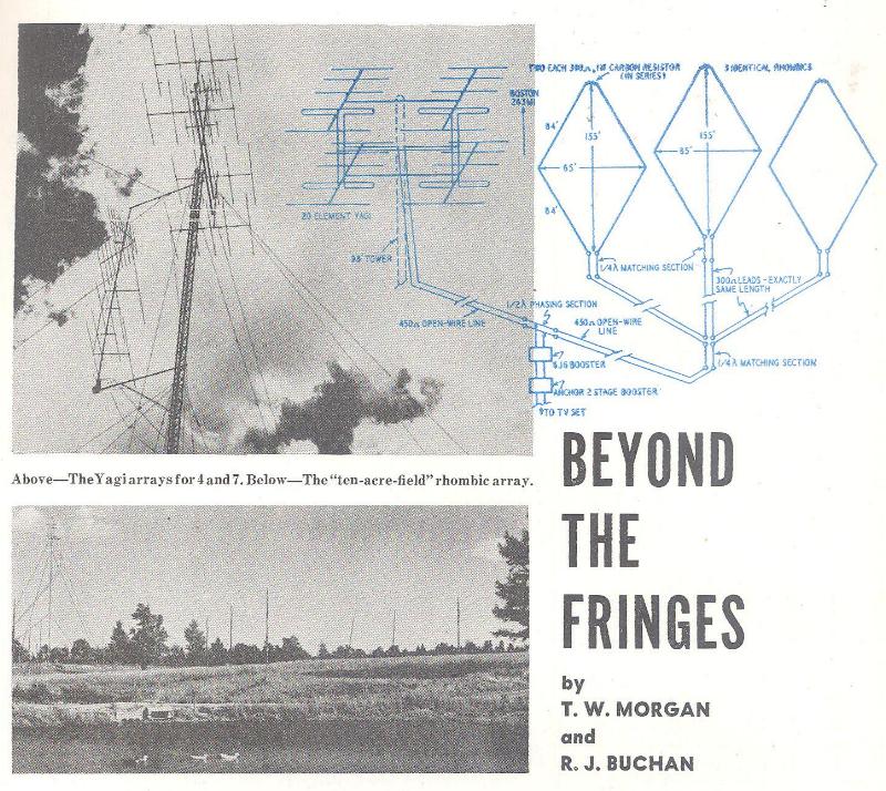
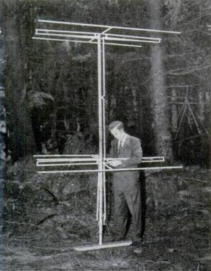
Thomas W. Morgan of West Pembroke, Maine might have disagreed with Telrex. Using great skill and attention to detail, he created a trio of phased side-by-side rhombics 155 feet long (covering ten acres), mounted on tall wood poles, pointing at Boston's WBZ-TV at a distance of 263 miles to his south, essentially over water the full distance (illustration below). The gain (in decibels) of this array would easily have been at least 24 dB — twice the 12-dB gain that Telrex claimed for channel 4.
Using this antenna in combination with a carefully-optimized home-built 6J6 booster (followed by a commercial two-tube Anchor commercial unit) Morgan found he could receive acceptable audio 75% of the time but viewable pictures only 30% of the time.
Writing in the March 1952 issue of Radio Electronics, Morgan and his co-author R. J. Buchan wrote:
"Improvements in antennas and receivers, plus increased transmitter power, have stretched the range of TV signals so that 75 to 150 miles is considered "fringe" by many stations. Thomas W. Morgan at West Pembroke, Maine, has succeeded in stretching this distance with an elaborate antenna system to an almost unbelievable 263 miles. Three large rhombics, 84 feet to a leg, in parallel with a 20-element Yagi, mounted on a 98-foot tower, for channel 4, plus an assortment of three arrays for channel 7, should qualify as the world's largest antenna receiving installation." Radio Electronics, March 1952
|
Telrex never provided similar information for their '300 mile over water' claim.
After his initial experiments in Tuckerman, Jimmy Davidson tackled a 'real' CATV system in nearby Batesville (114 miles to Memphis) by using a similar, if smaller, wire rhombic antenna, drawing on his U.S. Army-gained experience with such exotic items.
Antennas aside, none of these people — except for one — actually designed and built from scratch the entire active (excluding cable and passives) set of components necessary for reception of an acceptable signal from such distances. That person was none other than L.E. (Ed) Parsons.
Popular Mechanics (April 1950)
When Parsons decided to bring TV from Seattle to Astoria, he didn't let mountainous terrain discourage him. Above, he sets up a Channel 5 test antenna on one of the pine-covered hills near Astoria |
Parsons actually had a business plan — if not on Thanksgiving Day of 1948, then shortly thereafter. It was on his workbench and in his shop that he created the necessary components:
- Single-channel yagi antennas
- Single channel signal boosters
- Channel conversion converters
- Cable-powered in-line amplifiers
- Passive signal splitters
- Passive signal tap-off units
- Baluns to match the characteristic impedance of the coax (50 ohms unbalanced at the time) to the 300-ohm balanced TV set input terminals.
Parsons purchased military-surplus coaxial cable and hand-built everything else. I like to think of him as a "Milton Jerrold Shapp in a garage" — a one-man cable machine.
Parson's Astoria situation was unique and if in hindsight he might be faulted, it would be this that slowed him down. The signal from KRSC-TV transmitter, at a distance of about 125 miles from Astoria, arrived in what he called "finger-like-intrusions" in isolated segments of the city. After months of study, Parsons identified three of these "fingers."
Parsons may or may not have understood the underlying physics of this phenomenon, but by the mid-1950s, the cause had been identified as 'knife-edge-refraction' off the edges of mountain ridges in the line of sight between the KRSC-TV transmitting antenna and Parsons's receive site.
The Huygens-Fresnel principle
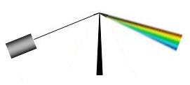 Knife edge refraction of white light. Cooper Knife edge refraction of white light. Cooper |
The knife-edge effect is explained by the Huygens-Fresnel principle, which states that a well-defined obstruction to an electromagnetic wave acts as a secondary source, creating a new wave front. This new wave front propagates into the shadow area of the obstacle.
The sketch at the right illustrates this effect with visible light. Note that the longer the wavelength (red) is refracted less than shorter wavelengths (blue).
In the case of Astoria, the obstructions in question were mountains in the path between the KRSC-TV transmitter site and Astoria. The following drawing illustrates the situation:
 Conceptual sketch of the profile of the path from the KRSC transmitter to the John Jacob Astor hotel in Astoria. Conceptual sketch of the profile of the path from the KRSC transmitter to the John Jacob Astor hotel in Astoria. |
Doty peak is a mountain near Doty, Washington at an elevation of approximately 2400 feet AMSL. It acted as a knife-edge refractor, redirecting the wave front toward Astoria as if the KRSC transmitter were at that peak rather than 65 miles beyond.
Astoria lies on the Oregon side of the Columbia River estuary ten miles upriver from the mouth of the river. Credit License |
The City of Astoria lies on a narrow coastal plain on the south bank of the Columbia River about ten miles upstream from the mouth of the river. The river itself is a tidal estuary at Astoria, rising and falling with Pacific tides. The ground elevation at Astoria varies from sea level to about 40 feet AMSL.
On the north side of the river, opposite Astoria, lies a series of mountain ridges of varying elevations, some of which rise to 800 feet above sea level. The terrain is typical of ancient mountain ranges: winding ridges of eroded peaks separated by deep, narrow valleys.
These ridges form a second knife-edge refractor. As Parsons would eventually discover, one of these ridges redirected the KRSC signal downwards toward Astoria.
Parsons had gone to considerable effort in his attempt to detect the KRSC signal at Astoria. He had installed, in his vehicle, a modified FM tuner capable of tuning to the KRSC aural carrier at 81.75 MHz. Using this tuner, he spent many hours 'probing' the community in search of signal. It was during these searches that he determined that the KRSC signal was indeed detectable in Astoria, but that it arrived in three distinct beams that he called "fingers."
During one of his interviews with Mary Alice Mayer Phillips and others, he reported that "the reception was like fingers extending from near ground level to some limiting height." At one location he detected the signal just above ground level, but after moving the test antenna up to an elevation of 80 feet, he found that the signal level was actually lower by about 15 dB.
Parsons apparently did not fully understand the significance of knife-edge-refraction to his success in detecting the signal of KRSC. It certainly cannot be said that he "invented" the technique; if anything, he stumbled across it during his 'probing' efforts. Nevertheless, he can be excused for not comprehending the mechanics of his fortuitous reception that through a chain of unique circumstances allowed him to pioneer an industry.
News of his discovery spread quickly. By mid-1949 Parsons was attracting coverage in the popular press:
Other entrepreneurs, hearing of this new technique, attempted to adopt it, with varying degrees of success, in mountainous regions elsewhere:
- The December 1950 issue of the British publication Practical Television included a detailed report from an enthusiast based in the Welsh coal-mining valley of Rhondda who had detected the signal of a BBC transmitter 94 miles distant. The report mentioned that the signal appeared in "beams" — the "fingers" that Parsons had detected at Astoria.
- The October 1955 issue of Proceedings of the IRE devoted essentially a full issue to the subject. Although quite technical, anyone plowing through these learned papers would no longer question the validity of what Parsons had done — seven years after Parsons identified the "fingers" in Astoria.
- The October 1961 issue of Television Horizons published an article by Bud Shepard of British Columbia-based Fred Welsh Antenna Systems stating that:
| In Squamish after no-result days of searching mountain tops for signs of signal from Seattle, a local asked "Have you talked with the fellow who has all three channels with an antenna hanging on the edge of his garage?" Sure enough - knife edge facing into the sharp side of a 6,000' mountain and his antenna location was 15' below sea-level! Or in Kaslo the only signal we found was 18 microvolts from channel 4 Spokane. Unfortunately the 'spot' where we found it was just above water level on a narrow beach jutting out
into Kootenay Lake. Two 80-foot towers were installed supporting 16 large yagi antennas. During the spring and summer water is released into the lake and the level rises so we constructed a log-boom to protect the array. Unfortunately a violent storm caused so much turbulence the boom broke and TV quit. We refound the 80-foot towers and the 16-yagi array
twenty feet under water! |
Even Parsons, believing that he had discovered some sort of "missing key" to distant TV reception, tried to capitalize on his discovery by offering a consulting service. He and his business partner Byron E. Roman established a plan: Parsons would equip a small private plane with signal-searching test equipment (81.75 MHz FM tuner and several exterior-to-cabin antennas) and begin routine flights over a large area in western Washington in an effort to help others identify the signal from KRSC-TV/KING-TV — for a fee.
Credit License
Bellingham is about 77 miles north of Seattle, near the Canadian border. |
The owners of AM radio station KVOS, located in Bellingham, Washington, signed up for the service. Bellingham is about 77 miles north of Seattle, close to the Canadian border. The station's engineers began serious construction in October 1949, eleven months after Parsons turned on his system in Astoria. They named their proposed system KVOS-TV, a name they would later use for an actual television station.
RTVN, June 1951
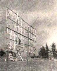
Side view of the Bellingham TV Antenna. The reflector screen, which measures 25 x 30 feet, consists of 32 half-wave elements. The screen is now seven feet from the ground, although tests indicate that the optimum elevation to be about 20 feet. |
Like Parsons, the KVOS engineers located the KRSC-TV/KING-TV signal on the far side of a 2,000-foot mountain range. By mid-1951 the company had installed a huge 32-dipole array functioning with a screen reflector, and was serving about 100 customers. It had planned to expand its network to a larger area, but was unable to reach a pole-attachment agreement with Pacific Telephone and Telegraph Co. It eventually reached a total of around 300 customers by attaching coaxial cable to privately-owned structures.
Parsons believed he had the knowledge and skills to allow others, no matter
where, to obtain similar results using this techniques and equipment. He seems to have missed an important point: the rolling hills of Pennsylvania — to say nothing of the Great Plains of Midwest — don't produce the same knife-edge refractions that he had observed when working in the shadows of the jagged mountains of the Pacific Northwest.
Nevertheless, Parsons and his partner Byron Roman established a nationwide CATV consulting business — doubtless the first such endeavor in history. Parsons charged for their time, and for the equipment they provided. According to Phillips' book, their sales inventory included:
High Gain' antenna . . . . $100.00
Channel converters
In-line amplifiers . . . .  $95.00  (We might call this a line extender today)
Two-way branching box  . . . $7.00  (We'd call this a two-way splitter today)
Three-way branching box  . . $8.50  (Three-way splitter)
Coaxial Cable, per foot  . . $0.083 (Erroneously quoted as $8.50 earlier in the book)
|
The Legacy of L.E. Parsons
 The Parsons story does not end happily. By mid-1953, he was in receivership and thirteen local people (virtually all of them cable subscribers) stepped in to take over what was claimed to be "the first American CATV system" (see Parsons Addendum). In the decades to follow, the Astoria system passed from hand to pocketbook and in 1968, when the granite monument was dedicated (May 23) Cox
Cablevision owned it.
The Parsons story does not end happily. By mid-1953, he was in receivership and thirteen local people (virtually all of them cable subscribers) stepped in to take over what was claimed to be "the first American CATV system" (see Parsons Addendum). In the decades to follow, the Astoria system passed from hand to pocketbook and in 1968, when the granite monument was dedicated (May 23) Cox
Cablevision owned it.
Parsons was an innovative creator of hardware to accomplish tasks which nobody appears to have done before. He was a born salesman, always on the lookout for some new product or service to sell.
He was also a maverick who left a legend of local history behind when transferring to Alaska. His AM radio station KAST, one of those granted a license after World War II to veterans under a special post-war US government FCC directive, covered the City of Astoria and Clatsop County with great devotion.
One of the many stories about Parsons relates how, without permission, he dug into the telephone company's underground ducts to install audio connections between the KAST radio studio and two local Astoria "nightspots." He intended for KAST to carry evening programming from the nightspots; unfortunately, the audio signal leaked into every telephone served by the Astoria exchange. The telephone company was not amused.
Stories like this partially illustrate why Parsons took the particular approach he did when creating his pioneering CATV service. He knew how to promote a product or a service by publicizing it in advance. After installing a functional receiving antenna on the roof of the John Jacob Astor Hotel in downtown Astoria, he connected the service to the lobby of the hotel and to Cliff Poole's music store across the street. Just as he had planned, word spread quickly. He was inundated by requests for service.
The logical way to extend the service would have been to use existing utility poles owned by Pacific Telephone and Telegraph company. But Parsons was reluctant even to approach the local telephone company manager. At one point, he inquired about the possibility in very off-handed way, but the manager, still smarting from the KAST incident and having zero comprehension of the request, dismissed him curtly.
So Parsons took the initiative. He began to string cables from building to building down Astoria blocks until he came to a new intersecting street. Here he would go out at night and clandestinely shove coaxial cable through city-owned storm drainage pipes to cross under the pavement.
This scheme worked for a while until city crews discovered the strange wire in their drainage pipes. So Parsons, ever innovative, faced with a street he could not get under or over, drew upon his technical expertise. On one side of the street he installed a Channel-2 line amplifier and connected it to feed a short yagi antenna. On the opposite side of the street he installed a receiving yagi, a new line amplifier, and continued merrily down the next block of houses.
By mid-1951 CATV systems were springing up all over North America. The Astoria city fathers had had their fill of what the Daily Astorian newspaper termed "Parsons' tinkering." One report related that "the city did not find [it] amusing."
Eventually, Parsons was granted a franchise modeled after other early franchises used in Pennsylvania. He also signed a 13-page pole attachment agreement with PT&T and Pacific Power and Light Company.
According to Phillips' book, at this stage Parsons had two primary antenna sites (each in a "finger") serving around 75 homes each, and 'numerous' (number not specified) smaller system sites serving between four and ten homes. In total, he was providing service to around 200 homes.
And so ends the story that originated when Parsons and his wife Grace attended the 1948 NAB
convention in Chicago, and Grace 'fell in love' with a demonstration of television sponsored by Coca-Cola. She would later tell Mary Alice Mayer Phillips, "I begged Ed to find a television set and bring TV to Astoria." Parsons obliged her but would, between the NAB convention and the first successful test pattern from KRSC-TV, be certain of only one thing: "Grace can cover it with a cloth and use it as a table when it does not work."
Author's postscript: The Old CATV Equipment Museum's hardware collection will never be complete without at least one item created by Ed Parsons. Whether Parsons marked his pieces with a name, a serial number or date is unknown — yet he tells us of "building hundreds of units for clients" using sheet metal chassis fabricated locally. The challenge is to find it if any still exists. It may be in Eldred or even Mahanoy City. Kudos to the industry person who finds it!
Oh yes ... if Ed Parsons is rightfully 'the father' of CATV, might not Grace
Parsons be 'the mother'?
—Bob Cooper, November 2011
In the continuation of this narrative, emphasis will shift from 'invention of' to 'perfection of' the CATV/cable concept from both the technical and business sides of the ledger.